This post has nothing to do with ham radio but it’s an electronics project that may be of interest.
 We bought a new car that turns out to be longer than the one we traded in, and parking it in our garage could be a potential problem (for both the car and the garage door) if it isn’t pulled in far enough. I wanted a better way to tell when the car was in far enough without using a sonar-based parking light (which I’ve found to be somewhat unreliable) or the old standby, hanging a tennis ball from the ceiling. I wanted a sensor to determine when the back edge of the car was past the garage door, and an indicator to tell when all is clear.
Our garage door opener comes with a pair of infrared sensors that will open the door if an object breaks the beam while the door is closing. I figured that if I could mount a second pair of sensors at bumper height, I could come up with a way to indicate when the car is in far enough. After looking through industrial supply catalogs for IR and laser sensor systems (most of which were expensive), I found that I was able to purchase another pair of garage door opener sensors at the local home improvement store, and I set out to figure out how they work.
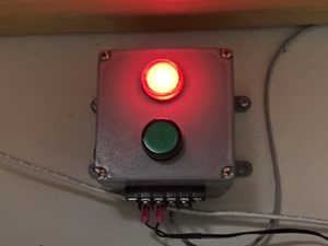
This particular sensor (for Genie openers) works by actually connecting them in parallel across a 12-volt DC supply. When the beam is complete, the units draw around 60 milliamps, and when the beam is broken, current draw drops to around 25 mA. I figured I could build a simple circuit to sense the current flow and turn on a light when the beam was unbroken. I wanted something a little more elegant and user friendly though. Instead of lighting just one light, I wanted two: a green “go” light and a red “stop” light. A small surplus SPDT relay did the trick.
I didn’t want the red light on all the time, though (current drain and lamp life isn’t an issue because I’m using LEDs) but I would like the red light to go off after a short delay, so additional components were added.
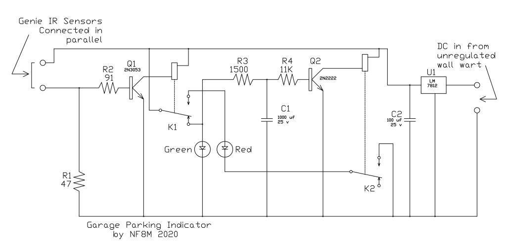
The circuitry is quite simple. Current to the sensors flows from the 12 volt supply through R1, and R2 biases the base of Q1 on when the higher current is drawn (and thus higher voltage drop across R1) indicating the path is clear. Q1 pulls up K1 providing power to the red LED (which is off because the return runs through K2, which is normally de-energized) and switching the green LED off. Whenever the beam is broken, the voltage drop across R1 dips, cutting off Q1, causing K1 to de-energize, switching the green LED on.
When the green LED is on, C1 charges through R3, biasing the base of Q2 on through R4. Q2 pulls up K2 when the green LED is on, providing a return path for the red LED. When K1 picks, 12 volts is provided to the red LED and C2 discharges through R4 to the base of Q2, causing Q2 to shut off after about eight seconds. K2 then drops out, opening the ground return to the red LED.
During development, it was found that the circuit performed differently if the supply voltage varied, so a means of regulating the supply was needed. Q3 is a 3-terminal regulator that holds the supply rail at a steady 12 volts. Power comes from a surplus wall wart that’s marked 12 volts but is unregulated and actually puts out around 18 volts. If a regulated wall wart is used, the onboard regulator probably isn’t necessary.
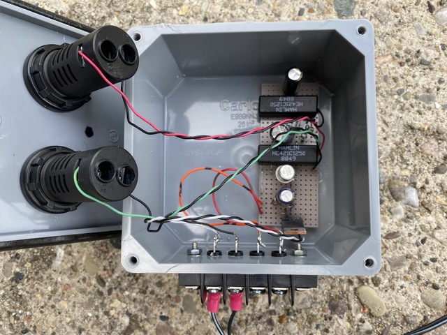 Most parts were recovered from my “junk box”. I purchased the breadboard, terminal strip and LEDs from Mouser and the sensors and enclosure (a 4x4x2 Carlon box) from Lowe’s. The most expensive part was the sensors, about $30. Wire to connect the sensors at the garage door to the box at the other end of the garage came from my supply of miscellaneous wire and cable, but a 50-foot spool of 2-conductor 24AWG or larger would work just fine.