 The latest project in the NF8M station is The Phaser. No, not the Star Wars kind. This one is a single-board phasing SSB transceiver that puts out about 4 watts and is designed for digital modes. It’s the brainchild of Dave, K1SWL and George, N2APB. (You may recall George and Milt W8NUE are the designers of the NUE-PSK standalone RTTY and PSK31 terminal. I have one of the early units and it’s a lot of fun!)
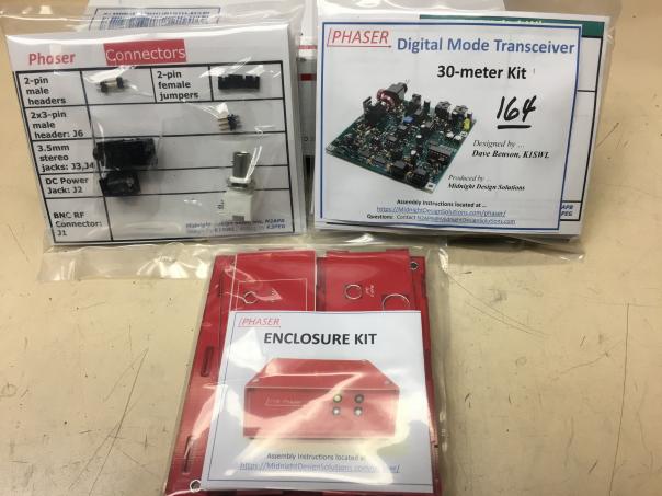 The Phaser comes in kit form and is available in single-band versions for 80, 40, 30, 20 and 17 meters, with additional bands on the drawing board. All that’s needed is a computer of some sort running a sound-card mode digital terminal program (wsjt or fldigi, for instance). It was primarily designed for FT8 but you could run any narrowband digital mode with it.
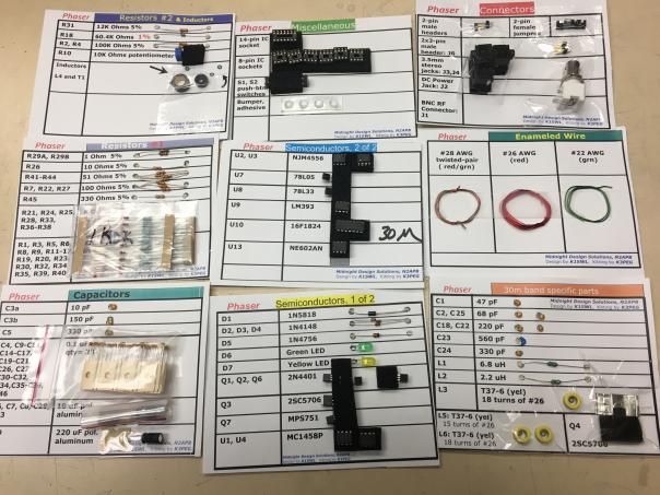 The kit comes with a handful of pre-installed SMD devices including the SI570 frequency synthesizer chip. The rest of the kit is all through-hole parts and socketed ICs. Four toroids need to be wound, but they’re not too difficult. Assembly instructions are very clear – Heathkit quality – and the parts come on cards, separated by type (resistors, ICs, etc.), labeled with the part number and value.
 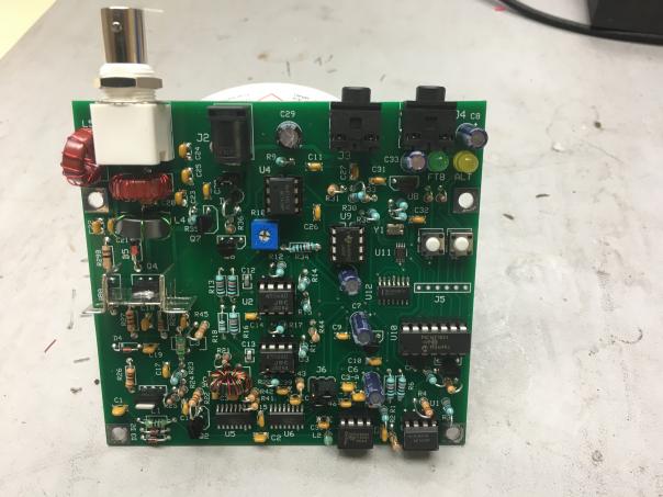 The synth controller, unique to each band, is pre-programmed for the FT8 “watering hole” frequency (7074 for the 40-meter version). There is a second channel available. As pre-programmed it’s set up for the JS8call frequency (7078) but it can be programmed for anywhere in the band, so you could set it up for the PSK31 frequencies of 7070 or 7040, or the new “overflow” FT8 frequency, 7071.
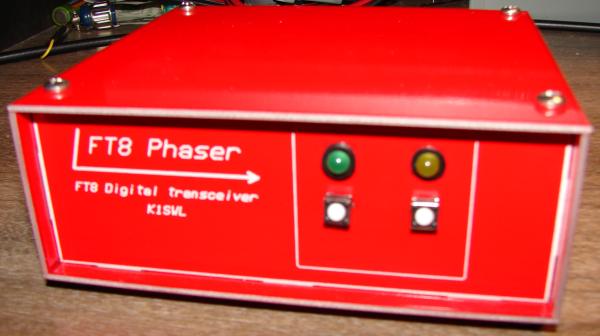
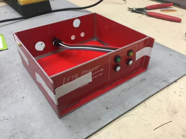 An optional case is available. It’s made of sturdy two-sided epoxy circuit board, coated in red etch resist with silk-screened labeling. The pieces are machined to fit together to form a box that you then solder along the inside edges. While you wouldn’t want to try bearing weight on it, the case is a useful addition to an elegant project. Switches and LEDs mount in holes drilled in the case, and are connected via traces on the inside side. The traces connect to a header on the circuit board with an included ribbon cable, which solders to etched pads on the case board.
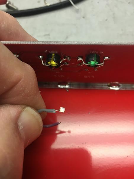 I found that in a couple instances, the pads delaminated from the board, necessitating soldering the wires to another point on the board. I brought this up with George, who made note of it for future design improvements.
It took me a total of almost four hours to assemble and test the Phaser. It’s built in six stages, with a function test at the end of each step so you’ll know if you’ve done all right so far. Once assembled, I put it on the air and worked two stations right away. I listened to the output in my Kenwood rig and it sounded clean.